Hardware Setup Guide
This guide walks you through everything needed to build an IR bridge from scratch — from choosing the right ESP32 board and IR components, through wiring and ESPHome configuration, to connecting it to your MQTT broker and IR2MQTT.
If you have never worked with microcontrollers or ESPHome before, start here. If you are already experienced, use the table of contents to jump to the section you need.
Table of Contents
- How Infrared Remote Control Works
- What You Need — Shopping List
- Choosing an ESP32 Board
- IR Hardware in Detail
- Wiring Guide
- Installing ESPHome
- ESPHome Firmware Configuration
- Flashing the ESP32
- Setting Up the MQTT Broker
- Installing IR2MQTT
- First-Run Walkthrough
- Verifying Your Hardware with the Loopback Test
How Infrared Remote Control Works
Before touching any hardware, a short theory block — knowing how IR remotes work will save you hours of debugging.
The carrier frequency
IR LEDs are not switched on and off at a visible rate. The signal is modulated: the LED pulses at a carrier frequency, most commonly 38 kHz (38,000 times per second). The receiver module is a band-pass filter tuned exactly to this frequency — it ignores ambient IR light (sunlight, lamps) and only passes through 38 kHz bursts.
When the receiver detects a burst, it pulls its output pin LOW. When there is silence, the pin goes HIGH. What comes out is a digital pulse train: a series of marks (pulse bursts) and spaces (silence), measured in microseconds.
Raw signal (not to scale):
LED:      ▁▁▁████████▁▁▁▁▁████▁▁▁████▁▁▁▁▁████████▁▁▁
Receiver: ████▁▁▁▁▁▁▁▁████████▁▁▁████████▁▁▁▁▁▁▁▁████
Protocols
These pulse trains are grouped into protocols. The most common ones are:
| Protocol | Used by | Notes |
|---|---|---|
| NEC | Most Asian TVs, ACs, cheap remotes | Very common. 32 bits: 8-bit address + 8-bit address inverted + 8-bit command + 8-bit command inverted. |
| Samsung | Samsung TVs | Similar to NEC but with different timing and a 64-bit variant. |
| Sony (SIRC) | Sony devices | 12, 15, or 20 bits. Uses pulse-width encoding. |
| RC5 / RC6 | Philips, Sky remotes | Biphase encoding (Manchester). RC5 is 14 bits, RC6 is 20+ bits. |
| Panasonic | Panasonic TVs, ACs | 48-bit frame with a 16-bit address. |
| RAW | Anything unrecognised | The fallback: stores the exact pulse/space timings in µs. |
If the ESP32 cannot decode a signal with a known protocol, it falls back to RAW — an array of signed integers where positive = mark duration in µs, negative = space duration in µs.
Why 940 nm?
IR LEDs emit light at around 940 nm — in the near-infrared spectrum, invisible to the human eye but detectable by photodiodes. When buying IR LEDs, make sure they are rated at 940 nm and not 850 nm (which is used for night-vision cameras and has different receiver sensitivity).
What You Need — Shopping List
Minimum (one WiFi bridge)
| Part | Notes | Approx. cost |
|---|---|---|
| ESP32 dev board (any variant, see below) | WROOM-32 or NodeMCU-32S is fine | €3–8 |
| IR receiver module (TSOP38238, VS1838B, or similar) | Must be 38 kHz, 3.3V or 5V compatible | €0.50–2 |
| IR LED 940 nm (e.g. TSAL6100, IR333C) | Get a few — they can burn out | €0.20–0.50 each |
| Resistor 33–100 Ω (for the IR LED current limiting) | ¼ W rating is enough | <€0.10 |
| Breadboard + jumper wires or PCB with solder | For prototyping or permanent installation | €2–5 |
| USB cable + power supply (5V / ≥500 mA) | Standard phone charger works | likely already available |
Optional but recommended
| Part | Notes |
|---|---|
| WS2812B (NeoPixel) single LED or strip | Status LED for the bridge — shows connection state, IR activity |
| High-power IR transmitter module (1 W variant) | Ready-made alternative to the transistor + LED circuit — connects like an IR receiver, no resistors needed. See below. |
| 2N2222 or BC547 NPN transistor | For a DIY high-power IR circuit (longer range) — any NPN you have lying around works for a single LED |
| 1 kΩ resistor | Base resistor for the transistor circuit |
| 100 µF electrolytic capacitor | Decoupling on the 3.3V rail — prevents brownouts during IR TX |
| 3D-printed enclosure or project box | For a clean installation |
Choosing an ESP32 Board
The ESP32 family has grown significantly. Here is what matters for this project:
ESP32 (original, Xtensa dual-core LX6)
The classic. All variants work perfectly with ESPHome and have 8 RMT channels (4 RX + 4 TX), which is what drives IR communication. This is the recommended choice if you have no preference.
| Board | Chip | Notes |
|---|---|---|
| ESP32-WROOM-32 (bare module) | ESP32-D0WDQ6 | The raw module — solder it yourself or use a breakout. |
| ESP32 DevKit v1 / NodeMCU-32S | ESP32-WROOM-32 | Breadboard-friendly, USB-Serial built in. Best for beginners. |
| WEMOS D32 / LOLIN32 | ESP32 | Compact, LiPo charging circuit, good build quality. |
| ESP32-WROVER | ESP32 + 4 MB PSRAM | More RAM — overkill for this project, but works fine. |
| ESP32-POE (Olimex) | ESP32 + LAN8720 | Has an Ethernet port. Ideal for a permanent wired bridge. |
| WT32-ETH01 | ESP32 + LAN8720 | Very compact Ethernet-capable board. Popular for smart home projects. |
Which one to buy for beginners?
Buy a ESP32 DevKit v1 (also sold as "NodeMCU-32S"). It costs ~€3–5, is breadboard compatible, has USB-Serial built in, and works with every ESPHome example in this guide without modification.
ESP32-S2 (Xtensa single-core LX7)
- Single core instead of dual core — fine for an IR bridge.
- 4 RMT channels (2 RX + 2 TX) — less than the original. Limit yourself to 2 receivers and 2 transmitters.
- No Bluetooth. Not a problem for this project.
- Fully supported by ESPHome.
ESP32-S3 (Xtensa dual-core LX7)
- More powerful than the original. Still 8 RMT channels (4+4).
- USB-OTG on-chip — some boards (e.g. the ESP32-S3-DevKitC-1) can do native USB.
- ESPHome support is mature. Good choice for a future-proof setup.
ESP32-C3 (RISC-V single-core)
- Very cheap (€2–3). Common in compact modules.
- Only 2 RMT channels — meaning maximum 1 receiver + 1 transmitter.
- Fully supported by ESPHome.
- Good if you need a tiny, cheap single-room bridge.
ESP32-C6 / ESP32-H2
- Newest variants. C6 has WiFi 6. H2 has Thread/Zigbee, no WiFi.
- ESPHome support is growing but still less mature. Not recommended unless you know what you are doing.
What about the original ESP8266?
The ESP8266 (NodeMCU, Wemos D1 Mini) does not have RMT hardware. ESPHome does support IR on the ESP8266, but falls back to software-based interrupt handling instead of dedicated hardware. The WiFi stack can preempt these interrupts, causing missed pulses — especially during IR reception. Transmitting usually works, but reliable decoding is not guaranteed. The ESP8266 is not recommended as a WiFi or MQTT bridge; use any ESP32 variant instead.
As a serial (USB) bridge, however, the situation improves: you can disable WiFi entirely in the ESPHome config, which eliminates the main source of interrupt interference. IR reception is noticeably more reliable in this mode. It is still software-based and not as solid as hardware RMT, but usable if an ESP32 is not available.
IR Hardware in Detail
IR Receiver Modules
An IR receiver is a three-pin integrated circuit that combines a photodiode, an amplifier, a band-pass filter (tuned to 38 kHz), and a demodulator. The output is a clean digital signal ready for a GPIO pin.
Popular choices:
| Part | Voltage | Frequency | Notes |
|---|---|---|---|
| TSOP38238 (Vishay) | 2.5–5.5V | 38 kHz | Industry standard. Low noise, excellent range (~45 m). Best pick. |
| TSOP1738 (Vishay) | 4.5–5.5V | 38 kHz | Older 5V-only version. Works fine with a 5V supply, but do not connect the output directly to a 3.3V GPIO without level shifting. Use TSOP38238 instead. |
| VS1838B | 2.7–5.5V | 38 kHz | Common cheap clone. Works, but noisier than TSOP. Good for prototyping. |
| TSOP4838 | 2.5–5.5V | 38 kHz | Similar to TSOP38238. Slightly different package. |
| SFH5110-38 (Osram) | 4.5–5.5V | 38 kHz | High-quality alternative. 5V-only output. |
5V output on a 3.3V GPIO
The ESP32 GPIO pins are not 5V tolerant. If your receiver is powered from 5V and outputs a 5V signal, you must add a voltage divider or a level shifter before the ESP32 GPIO pin. The safest option is to use a receiver that runs on 3.3V, like the TSOP38238.
Simple voltage divider with two resistors (10 kΩ + 20 kΩ) reduces 5V → 3.3V.
Pinout (front view, flat side facing you):
TSOP38238 / VS1838B
   ┌───┐
   │ ○ │  ← IR-sensitive lens
   └─┬─┘
    |||
    123
    │││
    ││└── Pin 3: VCC (2.5–5.5V)
    │└─── Pin 2: GND
    └──── Pin 1: OUT (signal → GPIO)
Note: Always check the datasheet for your specific part — some clones have VCC and GND swapped.
Bypass capacitor: Place a 100 nF ceramic capacitor between VCC and GND as close to the receiver as possible. This filters out high-frequency noise from the power rail and greatly improves reliability.
IR Transmitter LEDs
An IR LED works just like a visible LED, except it emits at 940 nm. To drive it from an ESP32 GPIO pin (which can only source ~12 mA), you need a current-limiting resistor.
Calculating the resistor:
R = (Vcc - Vf) / I_forward

Example: 3.3V supply, Vf = 1.2V (typical for TSAL6100), I = 50 mA
→ R = (3.3 - 1.2) / 0.05 = 42 Ω   → use 47 Ω

Example: 3.3V supply, 20 mA (safe for direct GPIO drive)
→ R = (3.3 - 1.2) / 0.02 = 105 Ω  → use 100 Ω
Direct GPIO drive (simple, short range):
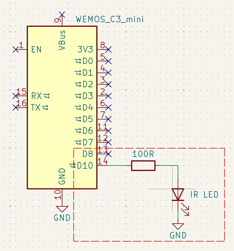
This is the easiest circuit. The LED will draw about 20 mA — within the GPIO current limit. Range is typically 3–5 metres with a good LED pointed at the device.
Popular IR LEDs:
| Part | Forward voltage | Max current | Notes |
|---|---|---|---|
| TSAL6100 (Vishay) | ~1.35V | 100 mA (peak) | High-intensity 5mm. Great all-rounder. |
| IR333C | ~1.2V | 100 mA (peak) | Common in Arduino kits. Fine for short range. |
| VSLB3940 (Vishay) | ~1.35V | 1 A (peak) | Very high power. Requires transistor circuit. |
| SFH4545 (Osram) | ~1.5V | 1 A (peak) | Narrow beam (±10°). Good for pointing at a specific device. |
High-Power Transmitter Circuit
For longer range (5–10+ metres) or when you need to cover a large room, use a transistor amplifier circuit that lets you drive the LED at much higher current (100–500 mA peak):
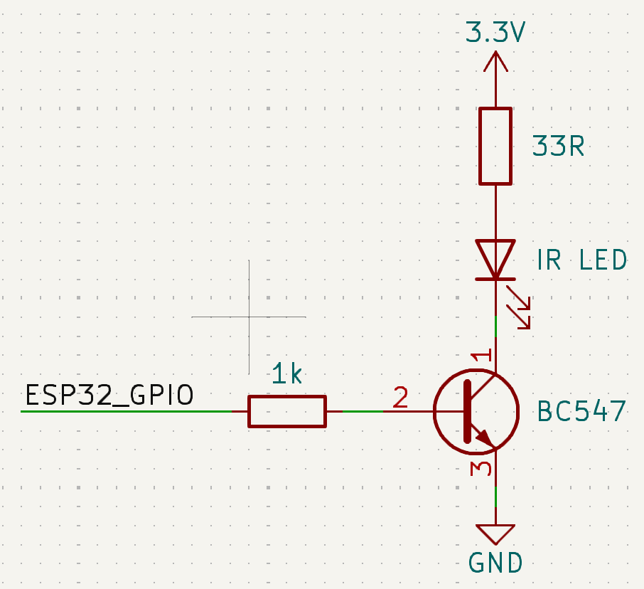
The pin numbers shown in the diagram refer to the physical legs of the transistor: pin 1 = C (Collector), pin 2 = B (Base), pin 3 = E (Emitter).
How it works: When the ESP32 GPIO goes HIGH, a small base current (~3 mA) flows through the 1 kΩ resistor into pin 2 (B). This turns the transistor on, closing the path from pin 1 (C) to pin 3 (E). Current can now flow from VCC through the resistor and LED, into the collector, and out the emitter to GND.
The GPIO never drives the LED directly — it only controls the transistor gate. At 3.3 V with a 33 Ω resistor: I = (3.3 − 1.35) / 0.033 ≈ 59 mA — nearly three times more than direct GPIO drive, at essentially no risk to the ESP32.
Which transistor to use — and when to switch to a MOSFET
The circuit above uses a BC547 (or 2N2222). These are classic small-signal NPN transistors that almost every hobbyist has collecting dust in a drawer somewhere — that is the only reason they appear in this example. They work fine for driving a single IR LED at ~50–100 mA.
Their limit: a BC547 is rated for a maximum collector current of 100 mA (2N2222: 600 mA). If you want to drive multiple LEDs in parallel at higher peak currents, it will get hot and may not switch cleanly enough to reproduce accurate IR pulse timing.
For the multi-LED circuits or if you want a more robust design, consider a logic-level N-channel MOSFET instead:
| NPN transistor (BC547, 2N2222) | N-channel MOSFET (e.g. 2N7000, BSS138, AO3400) | |
|---|---|---|
| Control method | Current-controlled: small base current opens the switch | Voltage-controlled: gate voltage opens the switch — virtually zero control current |
| Base/Gate resistor | Required (limits base current, e.g. 1 kΩ) | Optional (gate is high-impedance; small series resistor ~100 Ω is recommended to damp ringing) |
| 3.3V logic compatible | Yes (any NPN with Vbe ~0.6V) | Only if it is a logic-level MOSFET — check that Vgs(th) is below 2 V. Standard MOSFETs need 5–10 V to fully open. |
| Power handling | BC547: ~100 mA, 2N2222: ~600 mA | Depends on part — AO3400: 5.7 A continuous |
In practice, for a single IR LED at short-to-medium range the BC547 in a drawer is perfectly fine. For high-current multi-LED arrays, use a logic-level MOSFET.
Skip the discrete circuit entirely — ready-made high-power module
If you would rather not deal with the wiring, resistors, and transistor selection, there is a compact ready-made solution: a 1 W high-power IR transmitter module (shared by Reddit user dafunkjoker). It connects to the ESP32 exactly like an IR receiver module — just VCC, GND, and signal. No additional resistors or driver circuit needed.
The module is available on AliExpress (search for "1W IR transmitter module"). According to the spec sheet it covers 120° and up to 20–30 m. Community testing confirms it works reliably at ~7 m in a living room even pointing away from the device, which is a significant improvement over a direct-drive LED setup.
Multiple IR LEDs for wider coverage
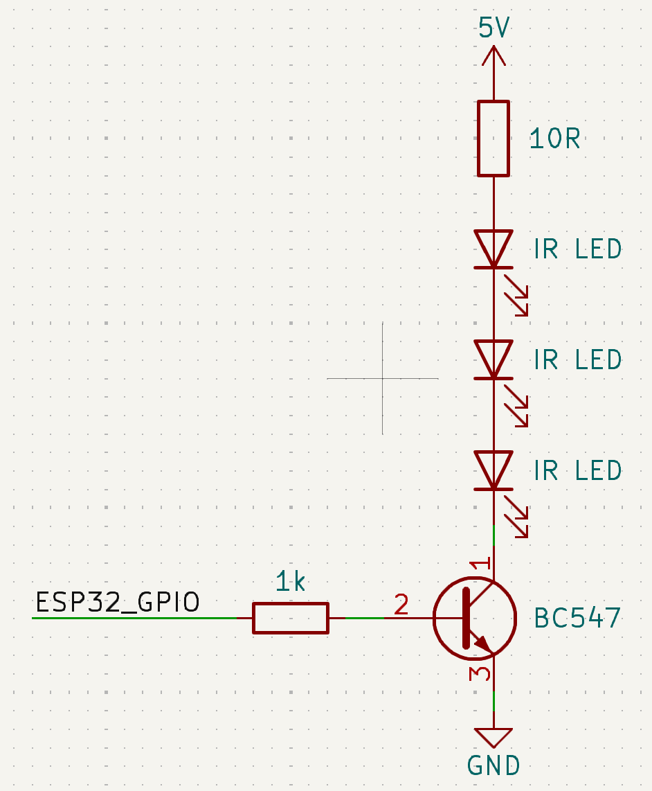
If a single LED doesn't cover the whole room, you can wire multiple LEDs — either in series or in parallel with individual resistors. Both circuits require a 5V supply and the transistor amplifier above.
Option A — Series (3 LEDs, 1 resistor):
Three LEDs in a chain. Each LED drops ~1.35V, so total Vdrop = 3 × 1.35 = 4.05V, leaving ~0.95V across the 10 Ω resistor. The same current flows through all LEDs — simple wiring, slightly lower current than parallel.
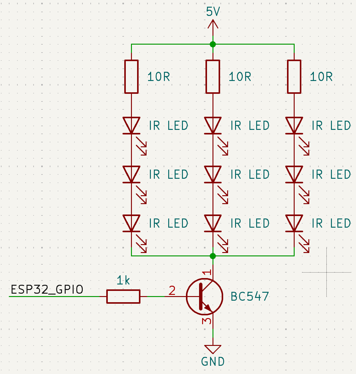
Option B — Parallel with individual resistors (3 LEDs, 3 resistors):
Each LED has its own 10 Ω resistor. All branches are connected in parallel. Current is shared independently per LED, so each LED runs at full brightness regardless of minor differences between them. More wiring, but more consistent output and wider spread if LEDs point in different directions.
Wiring Guide
All examples use an ESP32 DevKit v1 (or NodeMCU-32S). The GPIO numbers are suggestions — adjust them freely and update the ESPHome YAML to match.
Minimal setup: 1× Receiver + 1× Transmitter
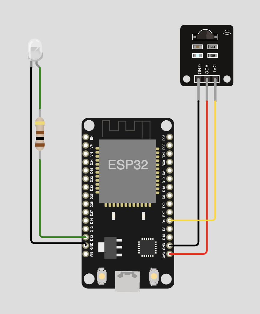
| Component | Pin | ESP32 pin |
|---|---|---|
| TSOP38238 | VCC | 3.3V |
| TSOP38238 | GND | GND |
| TSOP38238 | DAT | GPIO 4 |
| IR LED | Anode (+, long leg) | GPIO 13 via 100 Ω |
| IR LED | Cathode (−, short leg) | GND |
ESPHome configuration snippet
external_components:
  - source:
      type: git
      url: https://github.com/steelcuts/ir2mqtt_bridge
      ref: main
    components: [ir2mqtt_bridge]

remote_receiver:
  id: rx1
  pin:
    number: GPIO4
    inverted: true
    mode: INPUT_PULLUP
  rmt_symbols: 64

remote_transmitter:
  id: tx1
  pin: GPIO13
  carrier_duty_percent: 50%
  non_blocking: true
  rmt_symbols: 64

ir2mqtt_bridge:
  receivers: [rx1]
  transmitters: [tx1]
  device_id: "my-bridge"
With optional WS2812B status LED
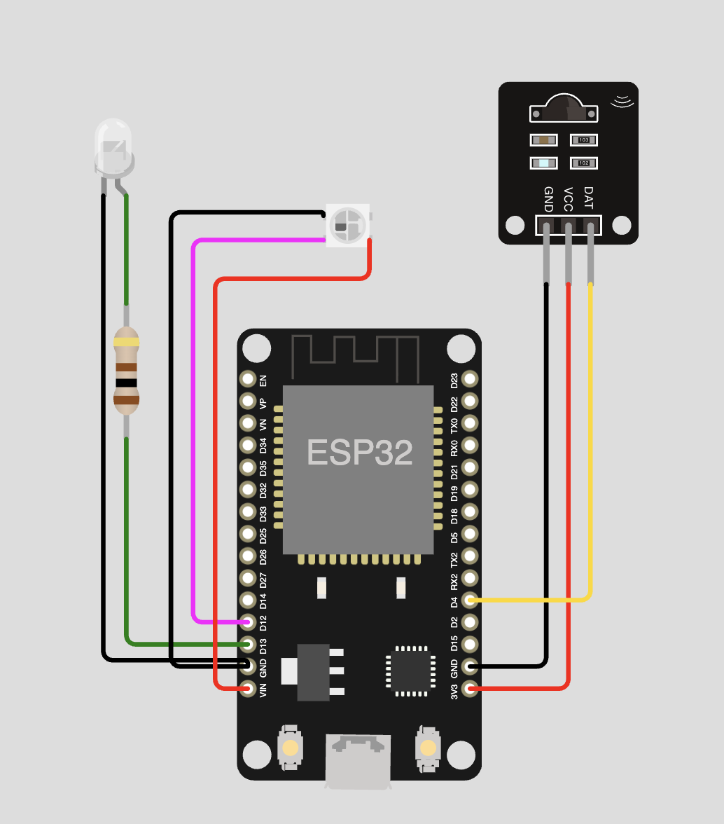
| Component | Pin | ESP32 pin |
|---|---|---|
| TSOP38238 | VCC | 3.3V |
| TSOP38238 | GND | GND |
| TSOP38238 | DAT | GPIO 4 |
| IR LED | Anode (+, long leg) | GPIO 13 via 100 Ω |
| IR LED | Cathode (−, short leg) | GND |
| WS2812B | VCC | 5V |
| WS2812B | GND | GND |
| WS2812B | DIN | GPIO 12 |
A WS2812 uses one RMT TX channel — keep this in mind if you plan multiple transmitters (see RMT Symbol Limit Explained).
ESPHome configuration snippet
external_components:
  - source:
      type: git
      url: https://github.com/steelcuts/ir2mqtt_bridge
      ref: main
    components: [ir2mqtt_bridge]

remote_receiver:
  id: rx1
  pin:
    number: GPIO4
    inverted: true
    mode: INPUT_PULLUP
  rmt_symbols: 64

remote_transmitter:
  id: tx1
  pin: GPIO13
  carrier_duty_percent: 50%
  non_blocking: true
  rmt_symbols: 64

light:
  - platform: esp32_rmt_led_strip
    id: status_light
    internal: true
    rgb_order: GRB
    chipset: WS2812
    pin: GPIO12
    num_leds: 1
    name: "IR Bridge Status LED"

ir2mqtt_bridge:
  receivers: [rx1]
  transmitters: [tx1]
  status_led: status_light
  device_id: "my-bridge"
Multi-room: 2× Receiver + 2× Transmitter
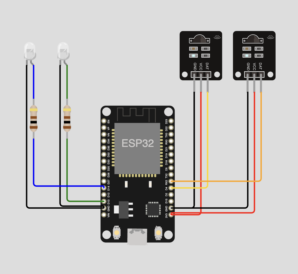
| Component | Pin | ESP32 pin |
|---|---|---|
| TSOP38238 #1 | VCC | 3.3V |
| TSOP38238 #1 | GND | GND |
| TSOP38238 #1 | DAT | GPIO 4 |
| TSOP38238 #2 | VCC | 3.3V |
| TSOP38238 #2 | GND | GND |
| TSOP38238 #2 | DAT | GPIO 16 / RX2 |
| IR LED #1 | Anode (+) | GPIO 13 via 100 Ω |
| IR LED #1 | Cathode (−) | GND |
| IR LED #2 | Anode (+) | GPIO 14 via 100 Ω |
| IR LED #2 | Cathode (−) | GND |
This uses 2 RX + 2 TX channels = 4 of 8 available RMT channels.
ESPHome configuration snippet
external_components:
  - source:
      type: git
      url: https://github.com/steelcuts/ir2mqtt_bridge
      ref: main
    components: [ir2mqtt_bridge]

remote_receiver:
  - id: rx1
    pin:
      number: GPIO4
      inverted: true
      mode: INPUT_PULLUP
    rmt_symbols: 64
  - id: rx2
    pin:
      number: GPIO16
      inverted: true
      mode: INPUT_PULLUP
    rmt_symbols: 64

remote_transmitter:
  - id: tx1
    pin: GPIO13
    carrier_duty_percent: 50%
    non_blocking: true
    rmt_symbols: 64
  - id: tx2
    pin: GPIO14
    carrier_duty_percent: 50%
    non_blocking: true
    rmt_symbols: 64

ir2mqtt_bridge:
  receivers: [rx1, rx2]
  transmitters: [tx1, tx2]
  device_id: "my-bridge"
Which GPIOs to avoid — by ESP32 variant
ESP32 (original / WROOM / DevKit)
- GPIO 6–11 — Internal SPI flash. Never use.
- GPIO 34, 35, 36, 39 — Input-only, no internal pull-up. Fine for receivers, but add an external 10 kΩ pull-up if your module doesn't include one. Cannot be used for TX.
- GPIO 0, 2, 12, 15 — Strapping pins. Affect boot mode if driven HIGH or LOW at reset. Avoid for IR.
ESP32-S2 / S3
- GPIO 26–32 (S2) or GPIO 27–32 (S3) — Internal flash/PSRAM on most modules. Check your board's schematic.
- GPIO 0 — Strapping pin (boot mode). Avoid.
- All remaining GPIOs are bidirectional — no input-only restriction like on the original ESP32.
ESP32-C3
- GPIO 11–17 — Internal flash on most modules. Check your board.
- GPIO 2, 8, 9 — Strapping pins. Avoid.
- Only 2 RMT channels total (1 RX + 1 TX) — plan accordingly.
When in doubt, consult the official datasheet or your board's pinout diagram before wiring.
Installing ESPHome
ESPHome is the firmware framework that turns your ESP32 into an IR bridge. You write a YAML configuration file, ESPHome compiles it into firmware, and flashes it to the device.
Option A: ESPHome Add-on in Home Assistant
This is the easiest method if you already run Home Assistant Supervised or Home Assistant OS.
- In Home Assistant, go to Settings → Add-ons → Add-on Store.
- Search for ESPHome and install it.
- Start the add-on and click Open Web UI.
- Click + New Device to create your first bridge configuration.
The web UI guides you through the initial setup wizard. You can also paste a full YAML directly into the editor.
Option B: ESPHome via pip (standalone)
If you do not run Home Assistant, install ESPHome as a Python package. Requires Python 3.9 or newer.
# Create a virtual environment (recommended)
python3 -m venv esphome-env
source esphome-env/bin/activate   # On Windows: esphome-env\Scripts\activate

# Install ESPHome
pip install esphome

# Verify installation
esphome version
The ESPHome command-line tool is now available. Create a folder for your config files and work from there:
mkdir my-bridges && cd my-bridges
# Create ir-bridge-livingroom.yaml with the config from the next section
esphome run ir-bridge-livingroom.yaml
Option C: ESPHome via Docker
docker pull esphome/esphome

# Run the ESPHome dashboard (web UI on port 6052):
docker run --rm -d \
  --name esphome \
  -v "${PWD}/esphome-configs:/config" \
  -p 6052:6052 \
  esphome/esphome

# Then open http://localhost:6052 in your browser
For serial flashing from Docker on Linux, pass the USB device:
docker run --rm \
  -v "${PWD}/esphome-configs:/config" \
  --device=/dev/ttyUSB0 \
  esphome/esphome run /config/my-bridge.yaml
ESPHome Firmware Configuration
Understanding the ir2mqtt_bridge Component
The ir2mqtt_bridge component is an external ESPHome component hosted in the ir2mqtt_bridge repository. You do not need to download anything manually — ESPHome fetches it automatically when it sees external_components: in your YAML.
The component wires together:
- One or more
remote_receivercomponents (your IR receiver modules) - One or more
remote_transmittercomponents (your IR LEDs) - MQTT publishing and subscribing
- Optional: UART serial communication
- Optional: WS2812 status LED
Example: WiFi Bridge (most common)
This is the configuration for a single-room WiFi bridge with one receiver and one transmitter.
# ir-bridge-livingroom.yaml

substitutions:
  device_name: ir-bridge-livingroom

esphome:
  name: ${device_name}
  friendly_name: "IR Bridge Livingroom"

esp32:
  board: esp32dev   # Works for most ESP32 DevKit / NodeMCU-32S boards
  framework:
    type: arduino

# Pull the ir2mqtt_bridge component from GitHub
external_components:
  - source: github://steelcuts/ir2mqtt_bridge
    components: [ir2mqtt_bridge]

# WiFi credentials — store sensitive values in secrets.yaml
wifi:
  ssid: !secret wifi_ssid
  password: !secret wifi_password
  ap:
    ssid: "${device_name} Fallback"
    password: "changeme123"

captive_portal:

# MQTT broker connection
mqtt:
  broker: !secret mqtt_broker      # e.g. 192.168.1.10 or core-mosquitto
  username: !secret mqtt_username
  password: !secret mqtt_password

# ESPHome logger and OTA updates
logger:
api:
ota:
  - platform: esphome

# IR Receiver on GPIO 14
remote_receiver:
  id: rx1
  pin:
    number: GPIO14
    inverted: true
    mode: INPUT_PULLUP
  rmt_symbols: 64

# IR Transmitter on GPIO 27
remote_transmitter:
  id: tx1
  pin: GPIO27
  carrier_duty_percent: 50%
  non_blocking: true
  rmt_symbols: 64

# The ir2mqtt_bridge component
ir2mqtt_bridge:
  receivers: [rx1]
  transmitters: [tx1]
  device_id: "livingroom"    # Becomes the MQTT topic: ir2mqtt/bridge/livingroom/...
  protocols:
    - nec
    - samsung
    - sony
    - raw
secrets.yaml (create this in the same folder, never commit it to git):
wifi_ssid: "YourWiFiNetwork"
wifi_password: "YourWiFiPassword"
mqtt_broker: "192.168.1.10"
mqtt_username: "mqtt_user"
mqtt_password: "mqtt_password"
Example: Ethernet / LAN Bridge
For a wired connection you need a board with an Ethernet PHY chip — the ESP32-POE (Olimex) or WT32-ETH01 are the most popular choices.
# ir-bridge-lan.yaml

esphome:
  name: ir-bridge-lan

esp32:
  board: esp32dev
  framework:
    type: arduino

external_components:
  - source: github://steelcuts/ir2mqtt_bridge
    components: [ir2mqtt_bridge]

# Ethernet configuration for ESP32-POE (Olimex)
ethernet:
  type: LAN8720
  mdc_pin: GPIO23
  mdio_pin: GPIO18
  clk_mode: GPIO17_OUT
  phy_addr: 0
  power_pin: GPIO12

# No wifi: block needed — Ethernet replaces it

mqtt:
  broker: !secret mqtt_broker
  username: !secret mqtt_username
  password: !secret mqtt_password

logger:
api:
ota:
  - platform: esphome

remote_receiver:
  id: rx1
  pin:
    number: GPIO36      # Input-only pin, fine for receiver
    inverted: true
    mode:
      input: true
  rmt_symbols: 64


remote_transmitter:
  id: tx1
  pin: GPIO4
  carrier_duty_percent: 50
  rmt_symbols: 64

# Optional WS2812 status LED
light:
  - platform: neopixelbus
    id: status_light
    type: GRB
    variant: WS2812X
    pin: GPIO16
    num_leds: 1
    name: "Bridge Status LED"

ir2mqtt_bridge:
  receivers: [rx1]
  transmitters: [tx1]
  device_id: "lan-bridge"
  status_led: status_light
  protocols:
    - nec
    - samsung
    - raw
WT32-ETH01 pin differences
If you use the WT32-ETH01 instead of the ESP32-POE, change the Ethernet pin configuration:
ethernet:
  type: LAN8720
  mdc_pin: GPIO23
  mdio_pin: GPIO18
  clk_mode: GPIO0_IN   # WT32-ETH01 uses GPIO0 for CLK input
  phy_addr: 1
And use GPIO39 for the receiver signal and GPIO2/4 for transmitters.
Example: Serial (USB) Bridge
A serial bridge connects the ESP32 directly to the machine running IR2MQTT via a USB cable. No WiFi, no MQTT broker needed between the ESP32 and the application — the JSON protocol runs over UART.
# ir-bridge-serial.yaml

esphome:
  name: ir-bridge-serial

esp32:
  board: esp32dev
  framework:
    type: arduino

external_components:
  - source: github://steelcuts/ir2mqtt_bridge
    components: [ir2mqtt_bridge]

# CRITICAL: Disable the ESPHome logger on UART0
# Without this, the logger will corrupt the JSON communication.
logger:
  baud_rate: 0

# UART configuration — UART0 is the default USB serial port
uart:
  id: bridge_uart
  tx_pin: GPIO1
  rx_pin: GPIO3
  baud_rate: 115200

remote_receiver:
  id: rx1
  pin:
    number: GPIO14
    inverted: true
    mode:
      input: true
      pullup: true
  rmt_symbols: 64


remote_transmitter:
  id: tx1
  pin: GPIO27
  carrier_duty_percent: 50
  rmt_symbols: 64

ir2mqtt_bridge:
  receivers: [rx1]
  transmitters: [tx1]
  uart_id: bridge_uart   # Enable serial mode
  device_id: "serial-bridge"
  protocols:
    - nec
    - samsung
    - raw
When the firmware is running, plug it into a USB port on the machine running IR2MQTT and add it as a serial bridge in the UI (click Add Serial Bridge on the Bridges page).
Serial bridge and WiFi
A serial bridge does not need WiFi or MQTT configured. But you can combine both: add both a wifi: block and a mqtt: block alongside the uart_id to have a bridge that works over both serial and network simultaneously. This is useful for development and debugging.
Example: Multi-Room Setup
Two receivers (left/right of room) and three transmitters (TV, soundbar, projector) with a status LED:
# ir-bridge-homecinema.yaml

esphome:
  name: ir-bridge-homecinema

esp32:
  board: esp32dev
  framework:
    type: arduino

external_components:
  - source: github://steelcuts/ir2mqtt_bridge
    components: [ir2mqtt_bridge]

wifi:
  ssid: !secret wifi_ssid
  password: !secret wifi_password

mqtt:
  broker: !secret mqtt_broker
  username: !secret mqtt_username
  password: !secret mqtt_password

logger:
api:
ota:
  - platform: esphome

# Receiver 1: front-left of the room
remote_receiver:
  - id: rx1
    pin:
      number: GPIO14
      inverted: true
      mode: { input: true, pullup: true }
    rmt_symbols: 64


# Receiver 2: front-right of the room
  - id: rx2
    pin:
      number: GPIO25
      inverted: true
      mode: { input: true, pullup: true }
    rmt_symbols: 64


# Transmitter 1: pointed at the TV
remote_transmitter:
  - id: tx_tv
    pin: GPIO27
    carrier_duty_percent: 50
    rmt_symbols: 64

# Transmitter 2: pointed at the soundbar
  - id: tx_soundbar
    pin: GPIO26
    carrier_duty_percent: 50
    rmt_symbols: 64

# Transmitter 3: pointed at the projector
  - id: tx_projector
    pin: GPIO32
    carrier_duty_percent: 50
    rmt_symbols: 64

# WS2812 status LED
light:
  - platform: neopixelbus
    id: status_light
    type: GRB
    variant: WS2812X
    pin: GPIO16
    num_leds: 1
    name: "Cinema Bridge LED"

ir2mqtt_bridge:
  receivers: [rx1, rx2]
  transmitters: [tx_tv, tx_soundbar, tx_projector]
  device_id: "homecinema"
  status_led: status_light
  protocols:
    - nec
    - samsung
    - sony
    - raw
This uses 2 RX + 4 TX (3 IR + 1 WS2812) = 6 of 8 RMT channels. Within limits.
GPIO Pin Selection Tips
| GPIO range | Notes |
|---|---|
| GPIO 0 | Boot mode selection. Pulled LOW by BOOT button. Avoid. |
| GPIO 1 (TX0) | UART0 TX. Used by default logger and serial bridge. Reserve for UART only. |
| GPIO 2 | Must be LOW at boot for flash mode. Many boards have an LED on it. Avoid for IR. |
| GPIO 3 (RX0) | UART0 RX. Reserve for serial bridge. |
| GPIO 4, 13, 14, 25, 26, 27, 32, 33 | General-purpose, work well for IR. Safe to use. |
| GPIO 12 | Must be LOW at boot (flash voltage strapping). Avoid unless careful. |
| GPIO 15 | Must be HIGH at boot (suppresses boot log). Avoid unless careful. |
| GPIO 16, 17 | Often connected to PSRAM in WROVER boards. Check your schematic. |
| GPIO 34, 35, 36, 39 | Input-only. No internal pull-up. Fine for receivers (inverted, active-low), but add a 10 kΩ pull-up externally if needed. Cannot be used for TX. |
| GPIO 6–11 | Connected to internal SPI flash. NEVER USE. Your device will crash. |
RMT Symbol Limit Explained
The ESP32's Remote Control Transceiver (RMT) peripheral is the hardware block that generates and decodes IR pulse trains. It uses on-chip SRAM buffers called "RMT symbols" — each symbol stores one mark/space pair.
- Total RMT channels: 8 (4 RX + 4 TX on original ESP32)
- Default ESPHome allocation: 192 symbols per channel = 3 channels consumed per receiver
- With
rmt_symbols: 64: 1 channel per receiver/transmitter
Why 64?
Most standard IR protocols (NEC, Samsung, Sony, RC5) fit in fewer than 64 symbols. A NEC frame is 34 pulse pairs = 34 symbols. 64 gives plenty of headroom while staying within 1 channel.
RAW signals can be longer. If you find that RAW captures are being cut off, try increasing to rmt_symbols: 128. This uses 2 channels instead of 1.
# Set on each receiver and transmitter:
remote_receiver:
  pin: GPIO14
  rmt_symbols: 64   # 1 channel used (instead of default 3)
  ...

remote_transmitter:
  pin: GPIO27
  rmt_symbols: 64   # 1 channel used
  ...
Flashing the ESP32
First Flash via USB
The very first time you flash a new device, it must be done over USB (USB-to-Serial connection). After that, you can use OTA.
Using ESPHome Dashboard (HA Add-on or Web UI)
- Open the ESPHome dashboard.
- Create or paste your YAML configuration.
- Click Install → Plug into this computer (if running locally) or Manual download (to get a
.binfile). - If using manual download, use the ESPHome Web flasher in your browser to flash the
.binvia USB.
Using ESPHome CLI
# Connect the ESP32 via USB, then:
esphome run my-bridge.yaml

# ESPHome will detect the port automatically on most systems.
# If it does not, specify the port:
esphome run my-bridge.yaml --device /dev/ttyUSB0
Putting the ESP32 into flash mode
Most dev boards have a BOOT button and a RESET (EN) button. If the auto-flash fails:
- Hold down BOOT.
- Press and release RESET (EN).
- Release BOOT.
- The chip is now in flash mode. Re-run the flash command.
USB drivers
On macOS and Windows, you may need to install a USB-Serial driver:
- CH340/CH341 chip (common on cheap NodeMCU boards): CH340 driver
- CP2102 chip (common on slightly better boards): CP210x driver
- FTDI chip: FTDI driver
If you are unsure which chip your board has, check the USB-Serial IC printed on the PCB near the USB port, or look up the board on AliExpress/Amazon.
On Linux, the drivers are built into the kernel. Make sure your user is in the dialout group:
sudo usermod -aG dialout $USER
# Log out and back in for the group change to take effect
Over-the-Air (OTA) Updates
Once the device is on your network and the initial firmware is flashed, all subsequent updates can be done wirelessly:
esphome run my-bridge.yaml
# ESPHome detects the device via mDNS and uploads OTA automatically
In the HA ESPHome add-on, click Install → Wirelessly for the same result.
Setting Up the MQTT Broker
MQTT is the messaging protocol that connects your ESP32 bridges to the IR2MQTT application. You need a broker (a server) that all clients connect to.
What is MQTT?
MQTT is a lightweight publish/subscribe messaging protocol. Clients either publish messages to a topic (a named channel, like ir2mqtt/bridge/livingroom/state) or subscribe to topics to receive messages. The broker routes messages from publishers to subscribers.
IR2MQTT uses MQTT to:
- Receive IR signals detected by the bridges
- Send IR commands to the bridges
- Discover bridges automatically when they come online
Option A: Mosquitto Add-on in Home Assistant
This is the simplest option if you run Home Assistant.
- Go to Settings → Add-ons → Add-on Store.
- Search for Mosquitto broker and install it.
- Start it with default settings.
- In Home Assistant, go to Settings → Devices & Services → MQTT and configure the integration — it auto-detects the Mosquitto add-on.
The Mosquitto add-on creates a local MQTT user matching your HA username. Note the hostname is core-mosquitto within the HA network (visible to other add-ons) and your HA host IP on port 1883 from outside.
For the ESPHome config, use:
mqtt:
  broker: core-mosquitto   # if ESPHome runs inside HA as add-on
  # — OR —
  broker: 192.168.1.x      # your HA host IP, if ESPHome is standalone
  username: your_ha_username
  password: your_ha_password
Option B: Standalone Mosquitto via Docker
# mosquitto/docker-compose.yml
services:
  mosquitto:
    image: eclipse-mosquitto:latest
    container_name: mosquitto
    restart: unless-stopped
    ports:
      - "1883:1883"
      - "9001:9001"    # WebSocket port (optional)
    volumes:
      - ./config:/mosquitto/config
      - ./data:/mosquitto/data
      - ./log:/mosquitto/log
Minimal config/mosquitto.conf:
listener 1883
allow_anonymous true   # For testing only! Use password_file in production.
persistence true
persistence_location /mosquitto/data/
For password authentication:
# Create the password file
docker exec -it mosquitto mosquitto_passwd -c /mosquitto/config/passwd mqtt_user
# Enter password when prompted

# Then update mosquitto.conf:
# allow_anonymous false
# password_file /mosquitto/config/passwd
Installing IR2MQTT
Option A: Home Assistant Add-on

- Click the badge above, or go to Settings → Add-ons → Add-on Store → ⋮ (top right) → Repositories and add
https://github.com/steelcuts/ir2mqtt-ha-app. - Refresh the page. Find IR2MQTT in the add-on store and click Install.
- Go to the Configuration tab and fill in your MQTT broker details:
mqtt_broker: core-mosquitto   # or your broker's IP
mqtt_port: 1883
mqtt_user: ""
mqtt_pass: ""- Click Save, then Start.
- Enable Show in sidebar if you want quick access.
- Click Open Web UI — you should see the IR2MQTT interface.
Option B: Standalone Docker
# docker-compose.yml
services:
  ir2mqtt:
    image: ghcr.io/steelcuts/ir2mqtt:latest
    container_name: ir2mqtt
    restart: unless-stopped
    ports:
      - "${APP_PORT:-8099}:${APP_PORT:-8099}"
    environment:
      - MQTT_BROKER=192.168.1.10     # Your broker's IP
      - MQTT_PORT=1883
      - MQTT_USER=mqtt_user
      - MQTT_PASS=mqtt_password
      - APP_MODE=home_assistant       # or 'standalone'
      - APP_PORT=8099                 # Change to use a different host port
    volumes:
      - ./data:/data
    # Only needed if you plan to use serial (USB) bridges:
    devices:
- /dev/ttyUSB0:/dev/ttyUSB0docker-compose up -dThe Web UI is now available at http://<your-host-ip>:8099 (or whichever port you set via APP_PORT).
Environment variables reference:
| Variable | Default | Description |
|---|---|---|
MQTT_BROKER | core-mosquitto | Hostname or IP of your MQTT broker |
MQTT_PORT | 1883 | MQTT broker port |
MQTT_USER | (empty) | MQTT username |
MQTT_PASS | (empty) | MQTT password |
APP_PORT | 8099 | HTTP port the application listens on |
APP_MODE | standalone | home_assistant enables MQTT auto-discovery in HA |
LOG_LEVEL | INFO | Logging verbosity (DEBUG, INFO, WARNING, ERROR) |
First-Run Walkthrough
With your ESP32 flashed and IR2MQTT running, here is what to do step by step.
Step 1: Watch the bridge come online
Open the IR2MQTT Web UI and navigate to Bridges. Within a few seconds of the ESP32 booting, it should appear as an online bridge. The bridge card shows its ID, IP address, firmware version, and enabled protocols.
If the bridge does not appear, check:
- Is the ESP32 connected to WiFi? (Check the ESPHome logs via USB or OTA)
- Is it connecting to the correct MQTT broker? (Check MQTT credentials in both the ESPHome YAML and IR2MQTT config)
- Are they on the same MQTT broker? (Both must publish/subscribe to the same broker)
Step 2: Test IR reception
Point your TV remote at the IR receiver and press a button. The Signal History on the bridge card (click the history icon ⏱) should light up with a received code entry. You should also see the status LED flash purple/magenta if you have one.
If nothing is received:
- Verify wiring: receiver OUT → GPIO, not swapped with VCC/GND
- Verify the GPIO number in your ESPHome YAML matches the physical wire
- Try a different protocol set — temporarily enable all protocols
- Test with a phone camera: IR LEDs on remotes are invisible to the eye but visible to most phone cameras (point the remote at your front camera and press a button — you should see a flash)
Step 3: Add a device
Go to Devices and click + Add Device. You can:
- Choose a template (TV, AC, Fan, etc.) for common button layouts
- Browse the IR Database for thousands of pre-loaded codes
- Create a blank device and add buttons manually
Step 4: Learn your first button
Open the device, click a button, and select Learn (or add a new button with the + icon and set it to learning mode). Point your remote at the receiver and press the corresponding button. IR2MQTT captures the code and saves it.
Smart Learning when multiple protocols are active
If your bridge has several protocols enabled and you are not sure which one will decode a signal, use Smart Learning. It collects 5 presses and picks whichever decoded code appeared most consistently across all of them — a simple majority vote. This is useful when a single press might be decoded by two protocols at once and you want the one that wins reliably. For a single known protocol, normal single-press learning is perfectly fine.
Step 5: Send a command
Click a learned button in the Web UI. The bridge should transmit the IR signal. Check that the device (TV, etc.) responds. If it does not respond:
- Confirm the IR LED is wired correctly (anode/cathode orientation)
- Point the ESP32 directly at the device and retry — range can be limited without a transistor circuit
- Check the Signal History to confirm a code was sent
Step 6: Check Home Assistant entities
If you are running the HA add-on, the App Mode is already fixed to home_assistant — there is no toggle to flip. As soon as IR2MQTT and Home Assistant are both connected to the same MQTT broker, discovery payloads are published automatically on startup.
If you are running standalone Docker, make sure APP_MODE=home_assistant is set in your docker-compose.yml (see Installing IR2MQTT).
In either case, go to Settings → Devices & Services → MQTT in Home Assistant — your IR devices should appear as entities (buttons, binary sensors, device triggers) without any manual YAML configuration.
Entities not showing up?
HA caches MQTT discovery payloads. If entities are missing after a fresh start, go to Settings → Devices & Services → MQTT, click Re-configure, and restart HA. Also make sure the MQTT integration in HA is connected to the same broker as IR2MQTT.
Verifying Your Hardware with the Loopback Test
The built-in Loopback Test is the fastest way to verify that your hardware actually works end-to-end.
- In the IR2MQTT Web UI, go to Settings.
- Scroll down to the Loopback Test card.
- Select a Sender (TX) bridge and a Receiver (RX) bridge — these can be the same device if the IR LED is positioned to point at the receiver.
- Start the test. IR2MQTT sends a series of known IR codes and waits for the bridge to receive them back.
If NEC and RC6 codes pass, your hardware is working correctly. These two protocols are good reference points: NEC is the most common IR protocol, and RC6 uses a different encoding scheme — if both survive the loopback, the TX/RX chain is solid.
Not all 30+ protocols use 38 kHz
IR2MQTT includes every protocol that ESPHome supports — over 30 in total. However, some of them (e.g. certain RF-based or proprietary protocols) do not use a standard 38 kHz carrier and are simply not compatible with a typical 38 kHz receiver module. A failed loopback result for an obscure protocol does not necessarily mean your hardware is broken. Focus on the common protocols (NEC, Samsung, Sony, RC6) as your baseline.
If common protocols consistently fail, check the basics:
- Verify polarity of the IR LED — reversed LEDs are a very common mistake (try flipping it)
- Confirm the receiver wiring matches the pinout in this guide (VCC/GND/OUT order varies by module)
- Try reducing the current-limiting resistor (use 47 Ω instead of 100 Ω) for a brighter signal at short range
- Check the ESPHome device logs for RMT channel errors
Something missing or not working as expected? The codebase is actively developed and primarily tested with standard IR hardware. If you hit a bug or a protocol that behaves unexpectedly, please open an issue on GitHub — there are templates for bug reports and feature requests.